|
|
|
|
Using well-seismic mistie to update the velocity model |
Next: Dipping Isotropic Example Up: Numerical Examples Previous: Numerical Examples
|
|
|
|
Using well-seismic mistie to update the velocity model |
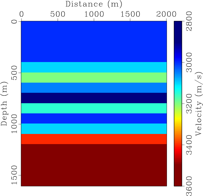
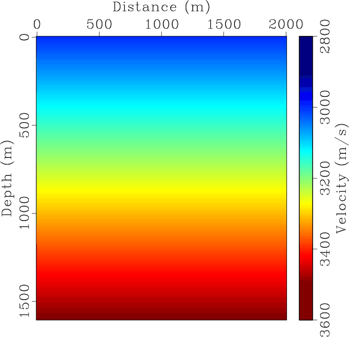
We model data using the true velocity model shown in Figure 2a, and the migration velocity is shown in Figure 2b. Because each layer is perfectly horizontal, we anticipate that the incorrect migration velocity will cause a discrepancy between the seismic image layer interfaces and the true interfaces from the velocity model.
|
|---|
|
vels,vel2
Figure 2. (a) True velocity model. (b) Initial migration velocity model. The velocity profile selected for the well tie update is located at 1000m. |
|
|
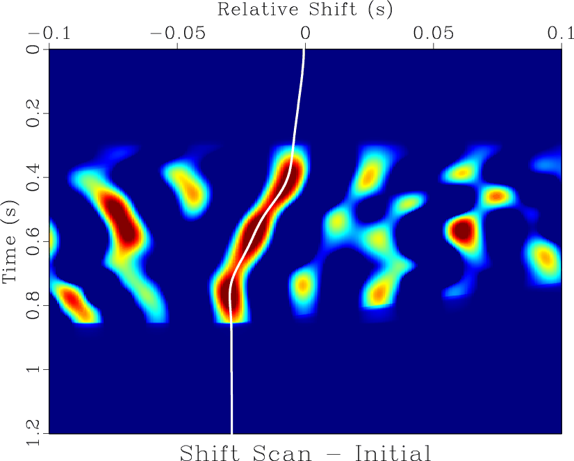
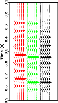
A seismic trace is extracted from the seismic image at location 1000m and compared against a modeled synthetic seismogram using a velocity `well log' from the true velocity mode at 1000m. The seismic-well tie is automatically carried out using LSIM and a mis-tie function is estimated using the LSIM scan in Figure 3. The mis-tie is used to tie the synthetic to the seismic trace in Figure 4 indicating the mis-tie function properly related synthetic and seismic traces.
|
|---|
|
scan2
Figure 3. Similarity scan using the seismic trace at 1000m, stretched to time using the well log velocity, as the reference trace compared against the synthetic seismogram modeled from the velocity profile extracted at 1000m in Figure 2b. |
|
|
|
|---|
|
synthp2
Figure 4. Initial synthetic seismogram (red). Synthetic seismogram stretched using the shifts estimated from LSIM scan in Figure 3 (green). Seismic trace extracted from RTM image stretched to time (black). |
|
|
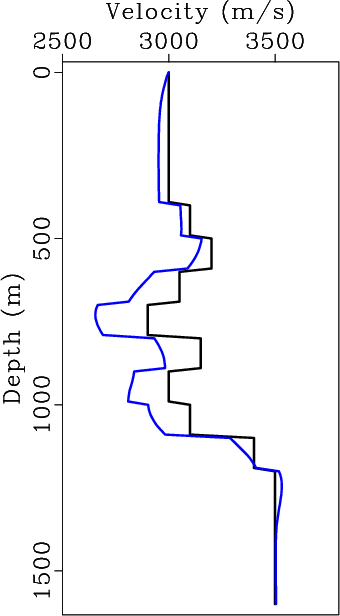
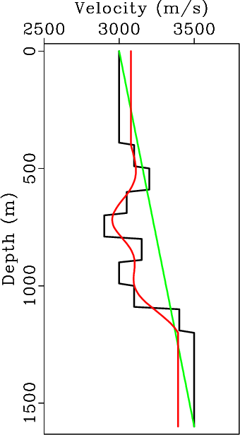
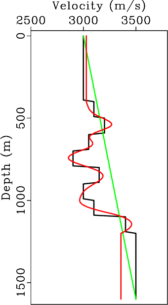
When working with the `final' seismic image, the mis-tie can be converted to a velocity log update as shown in Figure 5a. Alternatively, we use Equation 7 to update the migration velocity as shown in Figure 5b. After ten iterations of well tie updates, we observe that the migration velocity is consistent with the well log velocity in Figure 5c. Note that the updated migration velocity section above 400m and below 1200 is inconsistent with the real velocity as well ties are only possible in between the first and last impedance contrast in the well log data.
|
|---|
|
velupdate2,itr2,itrfi
Figure 5. Well log velocity profile (black). (a) Common workflow of applying the mistie from the synthetic-well tie in Figure 4 to update velocity log (blue). (b) Proposed approach of using the mistie from the synthetic-well tie in Figure 4 to update initial migration velocity (green) at the well location after one iteration (red). (c) Migration velocity profile at the well location after 10 iterations of well tie updates (red) |
|
|
The simple layered model provides the understanding that in isotropic velocity models, the primary reason behind the mis-tie between well log modeled synthetics and seismic data is in the accuracy of the seismic migration velocities. Assuming that the entire mis-tie is related to incorrect vertical positioning of the reflector, the migration velocity model can be effectively updated using Equation 7.
|
|
|
|
Using well-seismic mistie to update the velocity model |