|
|
|
|
Nonstationary pattern-based signal-noise separation using adaptive prediction-error filter |
As a kind of coherent noise in land survey, ground-roll noise always displays high amplitude, low frequency and low velocity. We created a synthetic model to examine the validity of the proposed method (figure 11a). The shot gather has low-frequency ground-roll noise and four hyperbolic reflection events, which overlap in the frequency domain (figure 11b). The linear ground-roll noise is generated by combining linear events with different dominant frequency, and its frequency range is limited from 0 to about 30 Hz. For comparison, the high-pass filter with a 25-Hz cutoff frequency produces the ground-roll noise separation result (figure 12). The nonstationary signal and ground-roll noise show the energy leakage in each other's sections because the frequency bandwidth of the ground-roll noise overlaps with that of the reflection events. Figure 13 shows the noise separation result by using the local time-frequency (LTF) decomposition (Liu and Fomel, 2013). In the time-frequency-space domain, we designed a muting filter to remove the ground-roll noise components, which leads to a higher SNR result (Table 2). By using the proposed method, the ground-roll noise can be separated in to the following steps (Fomel, 2002):
(i) Use a low-pass filter to roughly separate the ground-roll noise
as an initial estimation.
(ii) Make a mask from the initial noise model, and subsequent
separation process is restricted in this time-space window.
(iii) Calculate noise pattern
![]() from the noise model using APEF.
from the noise model using APEF.
(iv) Calculate data pattern
![]() from the origin data using APEF.
from the origin data using APEF.
(v) Further separate the signal and ground-roll noise based on
equation 7.
The noise model is made by the low-pass filter with a 12-Hz cutoff
frequency. We selected 12 (time) ![]() 3 samples (space) filter
coefficients for noise APEF
3 samples (space) filter
coefficients for noise APEF
![]() to predict the energy of
the steep ground-roll noise, the smoothing radius is set to be 20
(time)
to predict the energy of
the steep ground-roll noise, the smoothing radius is set to be 20
(time) ![]() 10 samples (space). Meanwhile, data APEF
10 samples (space). Meanwhile, data APEF
![]() has 7 (time)
has 7 (time) ![]() 4 samples (space) filter coefficients, the
smoothing radius is 40 (time)
4 samples (space) filter coefficients, the
smoothing radius is 40 (time) ![]() 30 samples (space).
The separated signal by using the proposed method is well recovered
(figure 14a), and the SNR of the denoised results is
comparable to that of LTF decomposition (Table 2).
The estimated noise section further verifies the successful signal-noise
separation (figure 14b). Although some noise at low
frequency is still present (figure 15d) and affects
the SNR, the energy of the effective signal is much cleaner after
using the proposed method.
30 samples (space).
The separated signal by using the proposed method is well recovered
(figure 14a), and the SNR of the denoised results is
comparable to that of LTF decomposition (Table 2).
The estimated noise section further verifies the successful signal-noise
separation (figure 14b). Although some noise at low
frequency is still present (figure 15d) and affects
the SNR, the energy of the effective signal is much cleaner after
using the proposed method.
| Synthetic model |
|
|
|
||||||||||||||||||||||
| SNR | -13.3 | 6.514 | 8.988 | 8.001 |


|
|---|
|
sp-synth,sp-compspt
Figure 11. (a) Synthetic shot gather containing ground-roll and (b) comparison of the spectrum. Solid line is the synthetic model, dashed lines the ground-roll noise (5 Hz dominant frequency) and reflection events (30 Hz dominant frequency). |
|
|


|
|---|
|
sp-bp,sp-bpnoiz
Figure 12. Noise separation results of the synthetic shot gather using the high-pass filtering. (a) Section of estimated signal and (b) section of separated ground-roll noise. |
|
|


|
|---|
|
sp-ltft,sp-ltftnoiz
Figure 13. Noise separation results of the synthetic shot gather using the LTF decomposition. (a) Section of estimated signal and (b) section of separated ground-roll noise. |
|
|


|
|---|
|
sp-apef,sp-apefnoiz
Figure 14. Noise separation results of the synthetic shot gather using the proposed method. (a) Section of estimated signal and (b) section of separated ground-roll noise. |
|
|


|
|---|
|
sp-fksynth,sp-fkbp,sp-fkltft,sp-fkapef
Figure 15. (a) F-K spectrum of the synthetic model. (b) F-K spectrum of the denoised result using the high-pass filtering. (c) F-K spectrum of the denoised result using the LTF decomposition. (d) F-K spectrum of the denoised result using the proposed method. |
|
|
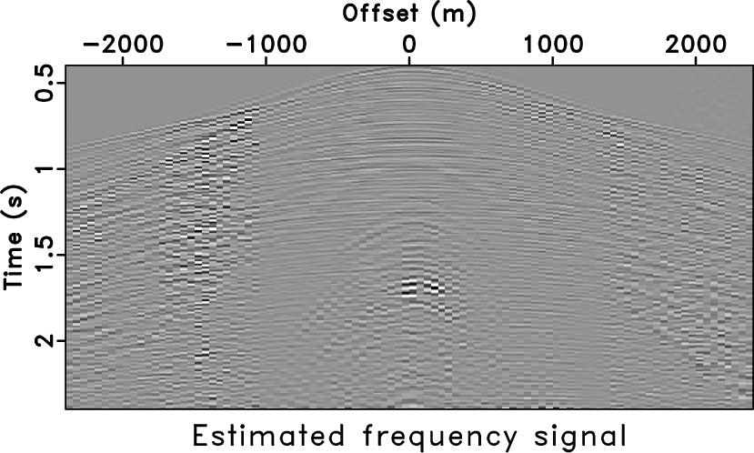
Figure 16 shows the profile and the corresponding
spectrum of a 3D land shot gather from Saudi Arabia, where the ground-roll
noise is three-dimensional and appears as a hyperbolic shape in this
receiver line. Due to the difference of dominant frequency between the
ground-roll noise and reflection events, it may suggest separating them
based on different frequency. The frequency-based separation method leads
to a worse result with a simple filter design, and the estimated
signal by using the high-pass filter with 20-Hz cutoff frequency
contains more low-level ground-roll noise (figure 17a).
The LTF decomposition method with a carefully selected muting filter
gets better results than those from high-pass filtering, but it still
leaves some ground-roll noise in the middle part of the estimated signal
section (figure 18a). We used the initial noise model
(figure 17b) to characterize the ground-roll noise,
noise APEF
![]() is designed with 12 (time)
is designed with 12 (time) ![]() 3 samples
(space) filter size and 20 (time)
3 samples
(space) filter size and 20 (time) ![]() 15 samples (space) smoothing
radius. Data APEF
15 samples (space) smoothing
radius. Data APEF
![]() uses a smaller filter size with 5 (time)
uses a smaller filter size with 5 (time)
![]() 4 samples (space) coefficients and 30 (time)
4 samples (space) coefficients and 30 (time) ![]() 25 samples
(space) smooth radius to capture signal energy. In the F-K spectrum
(figure 20d), there are also some weaker energies below 20 Hz,
but the ground-roll noise has been separated from the denoised results
(figure 19a). The proposed method achieved the separation
goal that the underlying reflection events clearly appear in the estimated
section, and the ground-roll noise is well suppressed.
25 samples
(space) smooth radius to capture signal energy. In the F-K spectrum
(figure 20d), there are also some weaker energies below 20 Hz,
but the ground-roll noise has been separated from the denoised results
(figure 19a). The proposed method achieved the separation
goal that the underlying reflection events clearly appear in the estimated
section, and the ground-roll noise is well suppressed.


|
|---|
|
dune-data,dune-spt
Figure 16. (a) A receiver line of the 3D shot gather and (b) the corresponding spectrum. |
|
|


|
|---|
|
dune-bp,dune-bpnoiz
Figure 17. Noise separation results of the field data using the high-pass filtering. (a) Section of estimated signal and (b) section of separated ground-roll noise. |
|
|


|
|---|
|
dune-ltft,dune-ltftnoiz
Figure 18. Noise separation results of the field data using the LTF decomposition. (a) Section of estimated signal and (b) section of separated ground-roll noise. |
|
|

|
|---|
|
dune-sign,dune-noiz
Figure 19. Noise separation results of the field data using the proposed method. (a) Section of estimated signal and (b) section of separated ground-roll noise. |
|
|


|
|---|
|
dune-dspec,dune-bspec,dune-lspec,dune-aspec
Figure 20. (a) F-K spectrum of the shot gather. (b) F-K spectrum of the denoised result using the high-pass filtering. (c) F-K spectrum of the denoised result using the LTF decomposition. (d) F-K spectrum of the denoised result using the proposed method. |
|
|
|
|
|
|
Nonstationary pattern-based signal-noise separation using adaptive prediction-error filter |