|
|
|
|
Structural uncertainty of time-migrated seismic images |

|
|---|
|
vlf
Figure 1. Velocity continuation cube for prestack time migration of the Gulf of Mexico dataset. |
|
|

|
|---|
|
npk
Figure 2. Migration velocity picked from velocity continuation. |
|
|

|
|---|
|
bei-agc
Figure 3. Seismic prestack time-migration image generated by velocity continuation. |
|
|
Velocity continuation is defined as the process of image
transformation with changes in migration velocity
(Fomel, 2003b,1994). Its output is equivalent to the output of repeated migrations with different migration velocities (Yilmaz et al., 2001) but
produced more efficiently by using propagation of images in
velocity (Hubral et al., 1996). If we denote the output of velocity
continuation as ![]() , where
, where ![]() and
and ![]() are time-migration
coordinates and
are time-migration
coordinates and ![]() is migration velocity, the time-migrated image is
simply
is migration velocity, the time-migrated image is
simply


|
|---|
|
slice,tslice
Figure 4. Common-image gather (a) and time slice (b) from velocity continuation with overlaid time-migration velocity. |
|
|


|
|---|
|
bei-dtdv,bei-dxdv
Figure 5. Estimated structural sensitivity in time (a) and lateral position (b) with respect to velocity. |
|
|
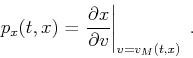
The structural sensitivity of an image can be described through
derivatives
![]() and
and
![]() , which
correspond to slopes of events in the
, which
correspond to slopes of events in the ![]() volume evaluated at
volume evaluated at
![]() . These slopes are easy to measure experimentally from the
. These slopes are easy to measure experimentally from the
![]() volume, using, for example, the plane-wave destruction
algorithm (Chen et al., 2013a,b; Fomel, 2002). Figure 4
shows one common-image gather
volume, using, for example, the plane-wave destruction
algorithm (Chen et al., 2013a,b; Fomel, 2002). Figure 4
shows one common-image gather
![]() for
for
![]() and the time slice
and the time slice
![]() for
for
![]() . Measuring the slope of events
. Measuring the slope of events
![]() in this gather and evaluating it at the picked migration velocity
produces the slope
in this gather and evaluating it at the picked migration velocity
produces the slope
Theoretically, structural sensitivity can be inferred from the zero-offset velocity ray equations (Fomel, 2003b; Chun and Jacewitz, 1981)
|
|
|
|
Structural uncertainty of time-migrated seismic images |