|
|
|
|
OC-seislet: seislet transform construction with differential offset continuation |
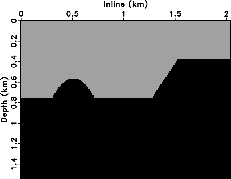
Figure 1 shows a 2-D slice out of the benchmark French
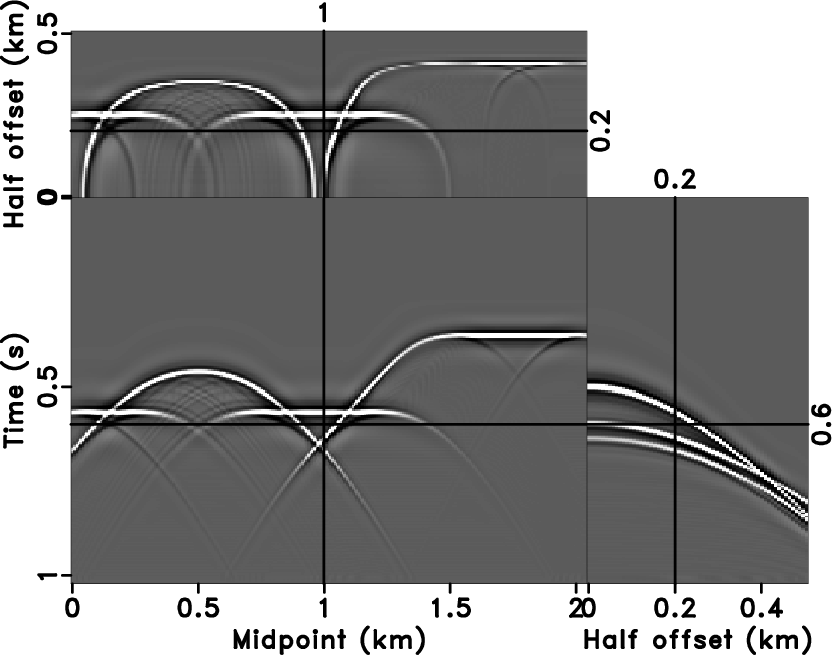
model (French, 1974). We created a 2-D prestack dataset
(Figure 2a) by Kirchhoff modeling. Three sections
in Figure 2a show the time slice at time position
0.6 s (top section), common-offset section at offset position of 0.2
km (bottom-left section), and common-midpoint gather at midpoint
position of 1.0 km (bottom-right section). The reflector with a round
dome and corners creates complicated reflection events along both
midpoint and offset axes. The inflection points of the reflector leads
to traveltime triplications at some
offsets. Figure 2b shows a preprocessed data cube
in the ![]() -
-![]() -offset domain after the log-stretched NMO correction
and a double Fourier transform along the stretched time and midpoint
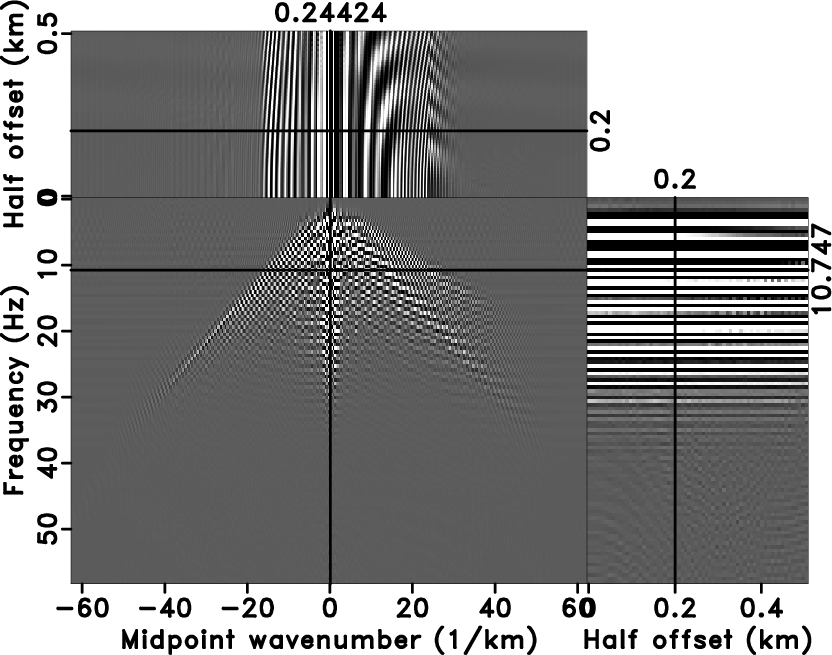
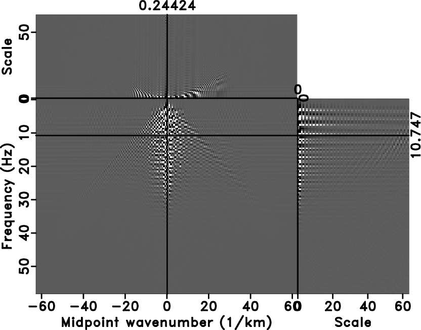
axes. We apply the OC-seislet transform described above along the
offset axis in Figure 2b. Thus, the offset axis
becomes the scale axis. The cube of the transform coefficients is
shown in Figure 3b and should be compared with
the corresponding Fourier transform along the offset direction in
Figure 3a. The OC-seislet transform
coefficients get concentrated at small scales, which enables an
effective compression. In contrast, the Fourier transform develops
large coefficients at coarser scales but has small residual
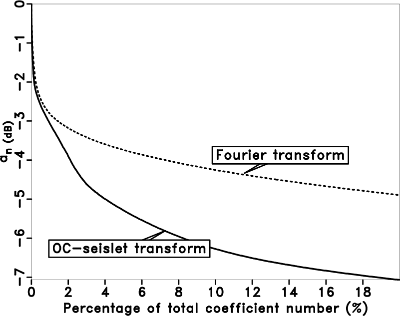
coefficients at fine scales. Figure 4 shows a
comparison between the decay of coefficients (sorted from large to
small) between the Fourier transform and the OC-seislet transform. A
significantly faster decay of the OC-seislet coefficients is evident.
-offset domain after the log-stretched NMO correction
and a double Fourier transform along the stretched time and midpoint
axes. We apply the OC-seislet transform described above along the
offset axis in Figure 2b. Thus, the offset axis
becomes the scale axis. The cube of the transform coefficients is
shown in Figure 3b and should be compared with
the corresponding Fourier transform along the offset direction in
Figure 3a. The OC-seislet transform
coefficients get concentrated at small scales, which enables an
effective compression. In contrast, the Fourier transform develops
large coefficients at coarser scales but has small residual
coefficients at fine scales. Figure 4 shows a
comparison between the decay of coefficients (sorted from large to
small) between the Fourier transform and the OC-seislet transform. A
significantly faster decay of the OC-seislet coefficients is evident.
|
|---|
|
slice
Figure 1. 2-D slice out of the benchmark French model (French, 1974). |
|
|
|
|---|
|
data,dinput
Figure 2. 2-D synthetic prestack data in |
|
|

|
|---|
|
dfourier,dtran
Figure 3. Fourier transform (a) and OC-seislet transform (b) of the input data from Figure 2b along the offset axis. |
|
|
|
|---|
|
compare
Figure 4. Transform coefficients sorted from large to small, normalized, and plotted on a decibel scale. Solid line: OC-seislet transform. Dashed line: Fourier transform. |
|
|
|
|
|
|
OC-seislet: seislet transform construction with differential offset continuation |