 |
 |
 |
 | Micro-earthquake monitoring with sparsely-sampled data |  |
![[pdf]](icons/pdf.png) |
Next: Interferometric imaging condition
Up: Micro-earthquake monitoring with sparsely-sampled
Previous: Introduction
Assuming data
 acquired at coordinates
 function of
time
function of
time  (e.g. in a borehole) we can reconstruct the wavefield
 at coordinates
 in the imaging volume using an
appropriate Green's function
in the imaging volume using an
appropriate Green's function
 corresponding to the
locations
and
(Figure 2)
corresponding to the
locations
and
(Figure 2)
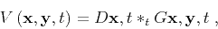 |
(1) |
where the symbol  indicates time convolution. The total
wavefield
indicates time convolution. The total
wavefield
 at coordinates
due to data recorded at
all receivers located at coordinates
is represented by the
superposition of the reconstructed wavefields
:
at coordinates
due to data recorded at
all receivers located at coordinates
is represented by the
superposition of the reconstructed wavefields
:
 |
(2) |
A conventional imaging condition (CIC) applied to this reconstructed
wavefield extracts the image
 as the wavefield at time

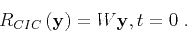 |
(3) |
This imaging procedure succeeds if several assumptions are fulfilled:
first, the velocity model used for imaging has to be accurate; second,
the numeric solution to the wave-equation used for wavefield
reconstruction has to be accurate; third, the data need to be sampled
densely and uniformly on the acquisition surface. In this paper, I
assume that the first and third assumptions are not fulfilled. In
these cases, the imaging is not accurate because contributions to the
reconstructed wavefield from the receiver coordinates do not interfere
constructively, thus leading to imaging artifacts. As indicated
earlier, this situation is analogous to the case of imaging with an
inaccurate velocity model, e.g. imaging with a smooth velocity of data
corresponding to geology characterized by rapid velocity variations.
Different image processing procedures can be employed to reduce the
random wavefield fluctuations. The procedure advocated in this paper
uses interferometry for noise cancellation. Interferometric procedures
can be formulated in various frameworks, e.g. coherent interferometric
imaging (Borcea et al., 2006) or wave-equation migration with an
interferometric imaging condition (Sava and Poliannikov, 2008).
coord
Figure 2. Illustration of the variables
and
used for the description of the conventional and
interferometric imaging procedures.
|

|
![[png]](icons/viewmag.png) ![[xfig]](icons/xfig.png)
|
|---|
|
|
|
|
| Micro-earthquake monitoring with sparsely-sampled data | |
|
Next: Interferometric imaging condition
Up: Micro-earthquake monitoring with sparsely-sampled
Previous: Introduction
2013-08-29