|
|
|
|
Isotropic angle-domain elastic reverse-time migration |
The images shown in the preceding subsection correspond to the
conventional imaging conditions from equations ![]() and
and ![]() . We can
construct other images using the extended imaging conditions from
equations
. We can
construct other images using the extended imaging conditions from
equations ![]() and
and ![]() , which can be used for angle decomposition
after imaging. Then, we can use equation
, which can be used for angle decomposition
after imaging. Then, we can use equation ![]() to compute angle
gathers from horizontal space cross-correlation lags.
to compute angle
gathers from horizontal space cross-correlation lags.
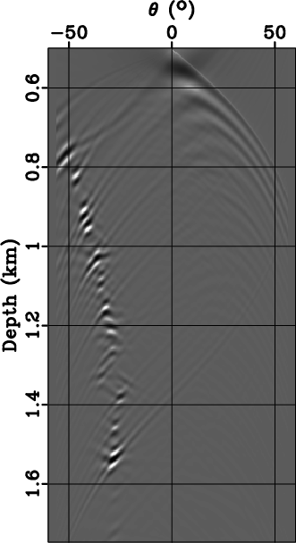
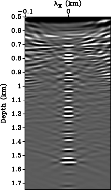
Figures ![]() and
and
![]() together with
Figures
together with
Figures ![]() and
and
![]() show, respectively, the PP and PS
horizontal lags and angle gathers for the common image gather (CIG)
location in the middle of the reflectivity model, given a single
source at
show, respectively, the PP and PS
horizontal lags and angle gathers for the common image gather (CIG)
location in the middle of the reflectivity model, given a single
source at ![]() km and
km and ![]() km. PP and PS horizontal lags are
lines dipping at angles that are equal to the
incidence angles (real incidence angles for PP reflection and
average of incidence and reflection angles for PS reflection) at
the CIG location. PP angles are larger than PS angles at all
reflectors, as illustrated on the simple synthetic example shown in
Figure 2.
km. PP and PS horizontal lags are
lines dipping at angles that are equal to the
incidence angles (real incidence angles for PP reflection and
average of incidence and reflection angles for PS reflection) at
the CIG location. PP angles are larger than PS angles at all
reflectors, as illustrated on the simple synthetic example shown in
Figure 2.
Figures 8a and 8c
together with Figures 8b and
8d show, respectively, the PP and PS
horizontal lags and angle gathers for the same CIG location, given
many sources from ![]() to
to ![]() km and
km and ![]() km. The horizontal
space cross-correlation lags are focused around
km. The horizontal
space cross-correlation lags are focused around
![]() ,
which justifies the use of conventional imaging condition extracting
the cross-correlation of the source and receiver wavefields at zero
lag in space and time. Thus, the zero lag of the images obtained by
extended imaging condition represent the image at the particular CIG
location. The PP and PS gathers for many sources are flat, since the
migration was done with correct migration velocity. The PS angle
gather, depicted in Figure 8d, shows a polarity
reversal at
,
which justifies the use of conventional imaging condition extracting
the cross-correlation of the source and receiver wavefields at zero
lag in space and time. Thus, the zero lag of the images obtained by
extended imaging condition represent the image at the particular CIG
location. The PP and PS gathers for many sources are flat, since the
migration was done with correct migration velocity. The PS angle
gather, depicted in Figure 8d, shows a polarity
reversal at ![]() as expected.
as expected.


|
|---|
|
je-0700-Ecig11,je-0700-Eang11,je-0700-Ecig12,je-0700-Eang12
Figure 7. Horizontal cross-correlation lags for (a) PP and (c) PS reflections for the model in Figures 3a and 3b. The source is at |
|
|


|
|---|
|
PPcig,PPcig-ang,PScig,PScig-ang
Figure 8. Horizontal cross-correlation lags for PP (a) and PS (c) reflections for the model in Figures 3a and 3b. These CIGs correspond to 81 sources from |
|
|
|
|
|
|
Isotropic angle-domain elastic reverse-time migration |