|
|
|
|
Dip and offset together |
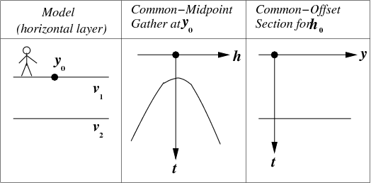
The simplest environment for reflection data is a single horizontal reflection interface, which is shown in Figure 8.6.
|
|---|
|
simple
Figure 6. Simplest earth model. |
|
|
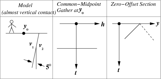
The next simplest environment is to have a planar reflector that is oriented vertically rather than horizontally. This might not seem typical, but the essential feature (that the rays run horizontally) really is common in practice (see for example Figure 8.9.) Also, the effect of dip, while generally complicated, becomes particularly simple in the extreme case. If you wish to avoid thinking of wave propagation along the air-earth interface you can take the reflector to be inclined a slight angle from the vertical, as in Figure 8.7.
|
|---|
|
vertlay
Figure 7. Near-vertical reflector, a gather, and a section. |
|
|
Figure 8.7 shows that the travel time does not change as the offset changes. It may seem paradoxical that the travel time does not increase as the shot and geophone get further apart. The key to the paradox is that midpoint is held constant, not shotpoint. As offset increases, the shot gets further from the reflector while the geophone gets closer. Time lost on one path is gained on the other.
A planar reflector may have any dip between horizontal and vertical.
Then the common-midpoint gather lies between
the common-midpoint gather of Figure 8.6
and that of Figure 8.7.
The zero-offset section in Figure 8.7 is a straight line,
which turns out to be the asymptote of a family of hyperbolas.
The slope of the asymptote is the inverse of the velocity ![]() .
.
It is interesting to notice that at small dips, information about the earth velocity is essentially carried on the offset axis whereas at large dips, the velocity information is essentially on the midpoint axis.
|
|
|
|
Dip and offset together |